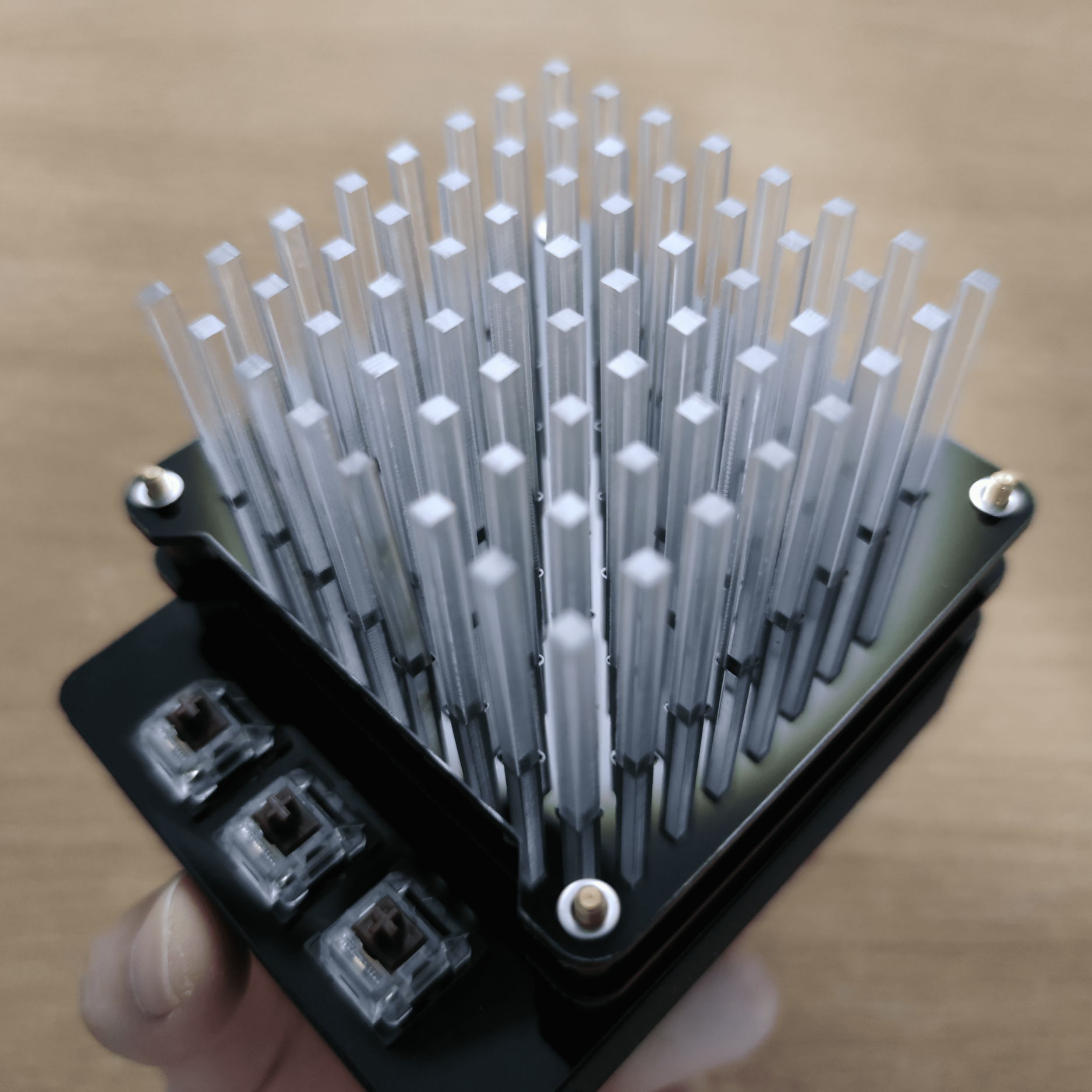
I wanted to make a audio visualiser for the fun of it. The audio visualiser consist of 4 simple parts: Base Plate, Cover Plate, Support Layer Plates, Acrylic Sticks. I took reference from a design made by a youtuber. I added my own changes such as to mount the mechanical buttons & microphone. RGB Laser Stem VideoThe difference between my project and his project is that I use the microphone to make music reactive LEDs. Whereas his project, which has no other input components, have very beautiful lighting features.
Design
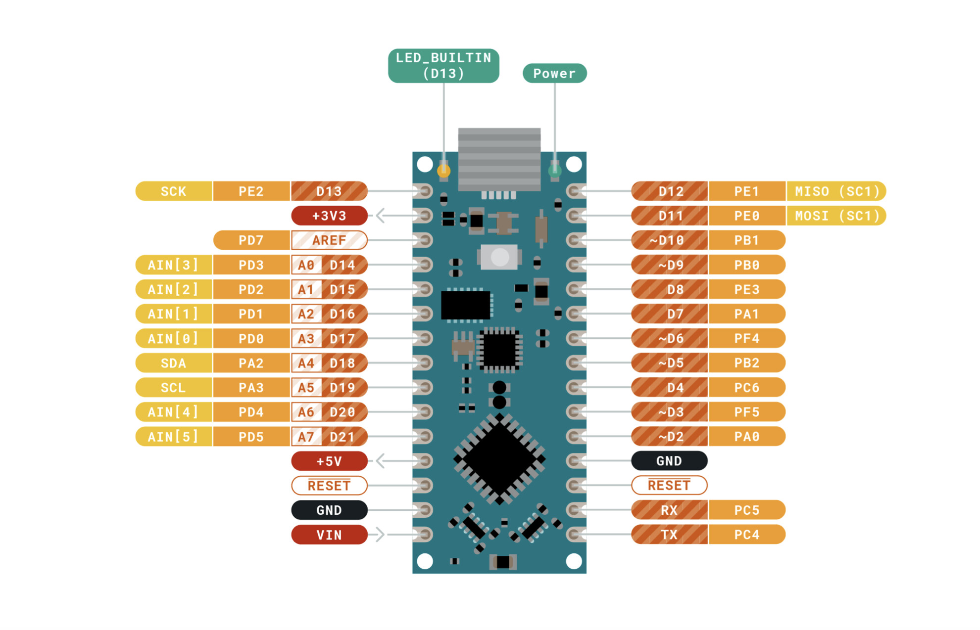
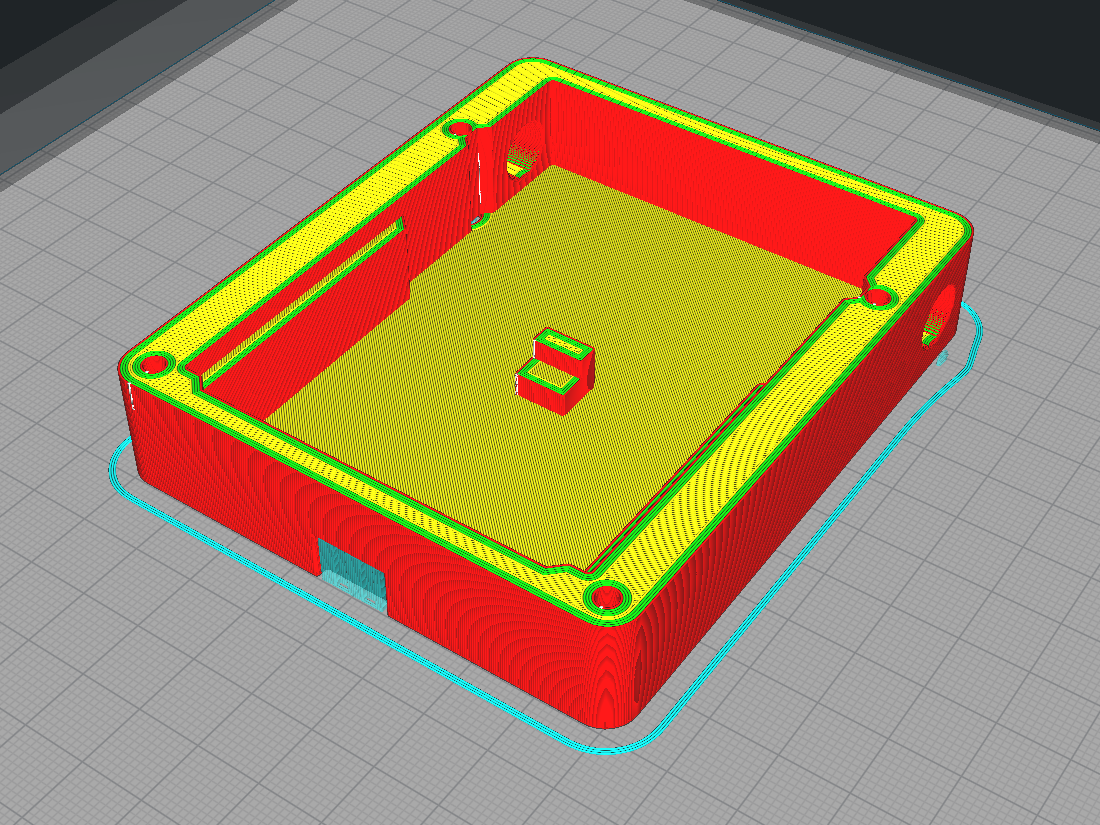
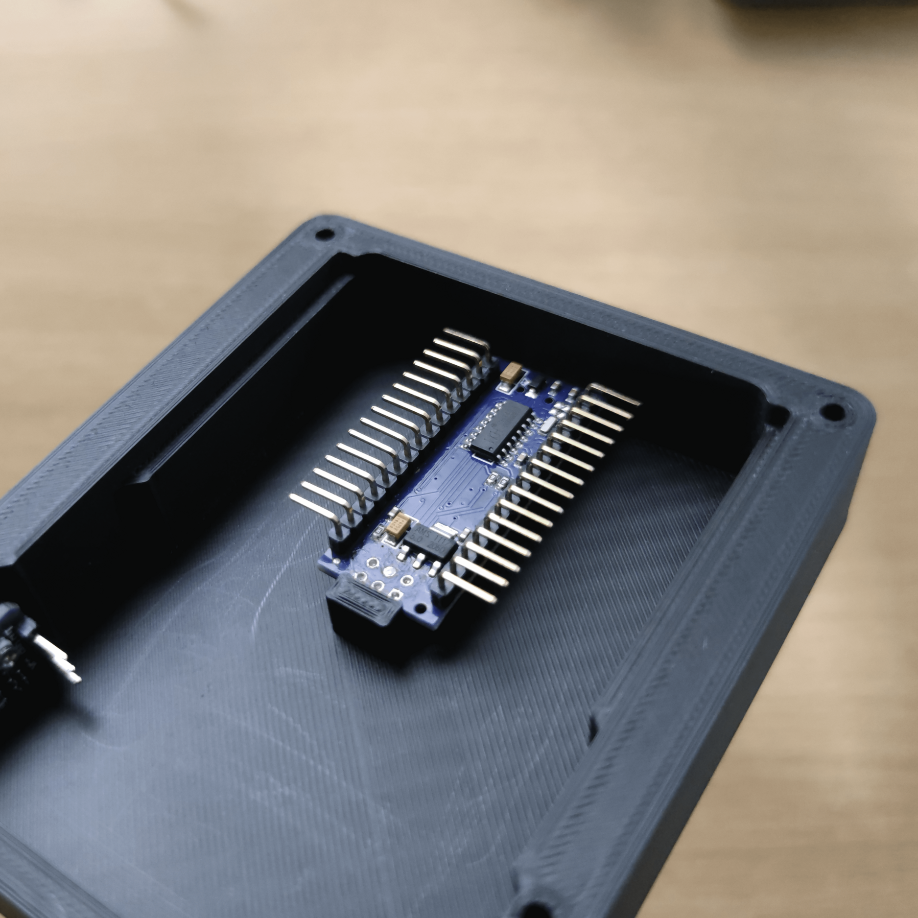
Circuit Planning
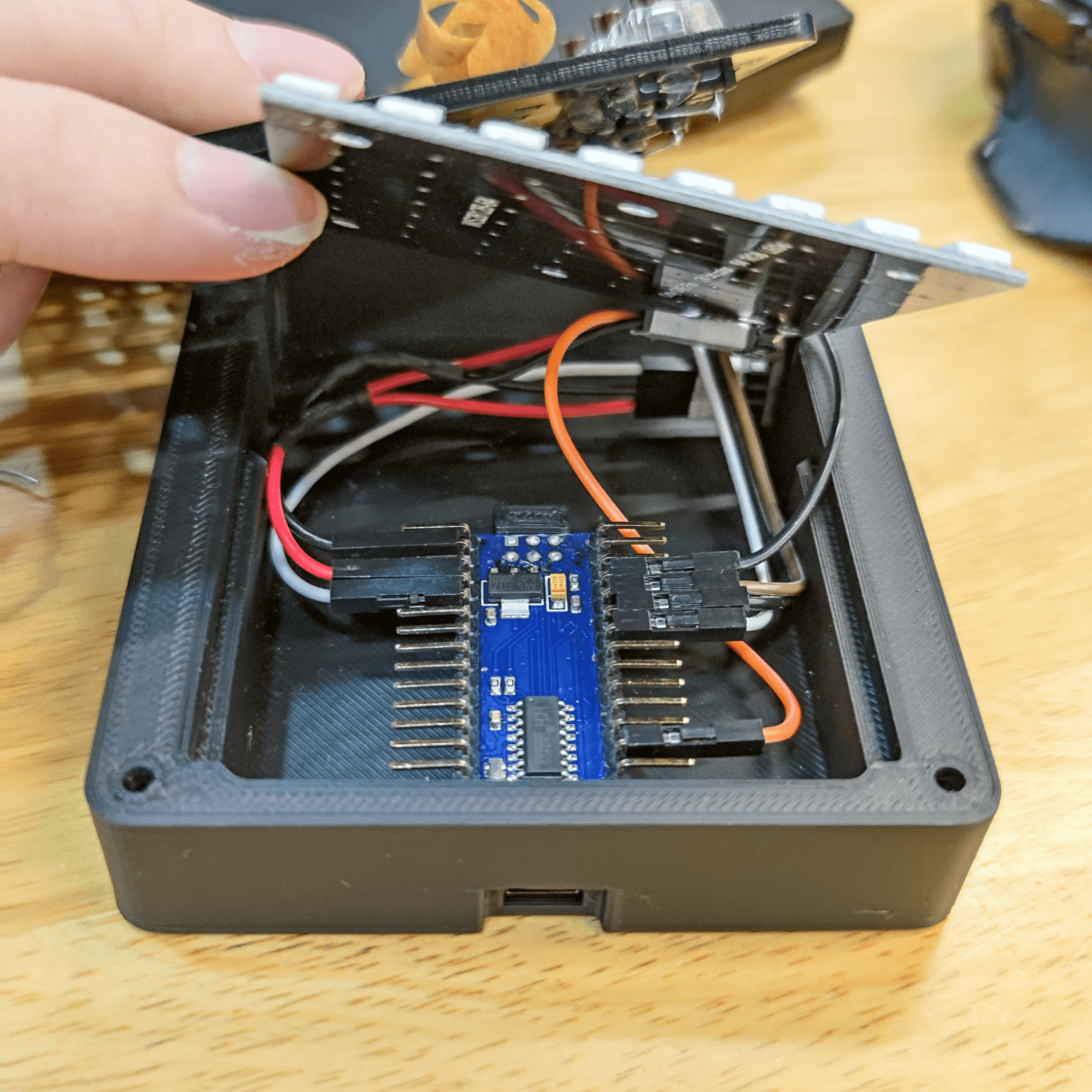
I designed a 3D printed base to mount my mount my components so that if there were any hardware errors, I can easily dismantle and fix. I will need to plan and consider how I will want to connect my wires for the componenets inside the 3D printed base. I am also a very big fan of low profile and compact designs. I had resolder the Arduino Nano by replacing the straight header pins to L-header pins because managing jumper wires will be easier sideways. Reason behind using jumper wires because I generally do not like to make connections too permananent despite experienced with lose connections. However, in a small space for wires, they are not easily disconnect.
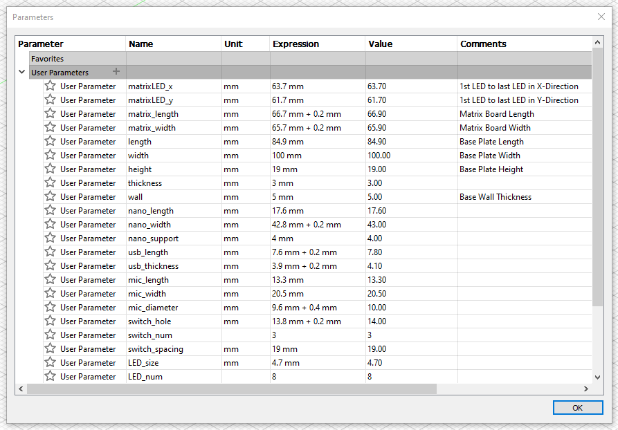
Parameters
This is the parameters settings I use for my audio visualiser. I took a lot of measurements around components and set them as parameters as shown. I set the tolerance around 0.2mm to 0.4mm to fit my components in.
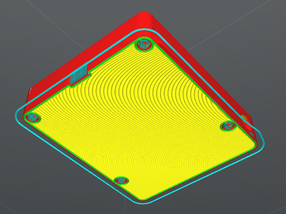
This is my completely parametric RGB Audio Visualiser design model.
The audio visualiser plates are exported as DWG files and opened in CorelDraw to laser cut. I offset each plate to around 1mm so that little amount of material is wasted cutting around them.
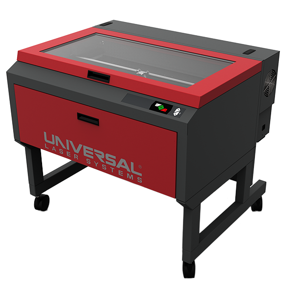
Laser Cutter
Universal VLS6.60
Vector
Speed 7%Power 40%PPI 600
Files
Audio Visualiser Plates
Acrylic Sticks
There are a total of 3 plate pieces and 64 acrylic Sticks to laser cut. The laser cutting went well and there were no problems at all. The acrylic sticks fit perfectly into the holes of the audio visualiser plates.
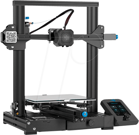
As for 3D printing, I took 3 attempts. The 1st attempt is that the dimensions were all completely wrong as I used dimensions in the wrong areas during modelling. Hence the components are unable to fit inside. The 2nd attempt is that I added too little tolerance of 0.1mm. Most of the components could not fit into the base due to either too tight or unable to fit through. Luckily, I use an infill of 5% my test print and the design is parametric. The 3rd and final attempt is to adjust the values in the parameters to the optimal values. The final print took around 3 hours which is may not be ideal for most some cases. Once it was done, the components are able to fit into the mounting slots.
Assembly
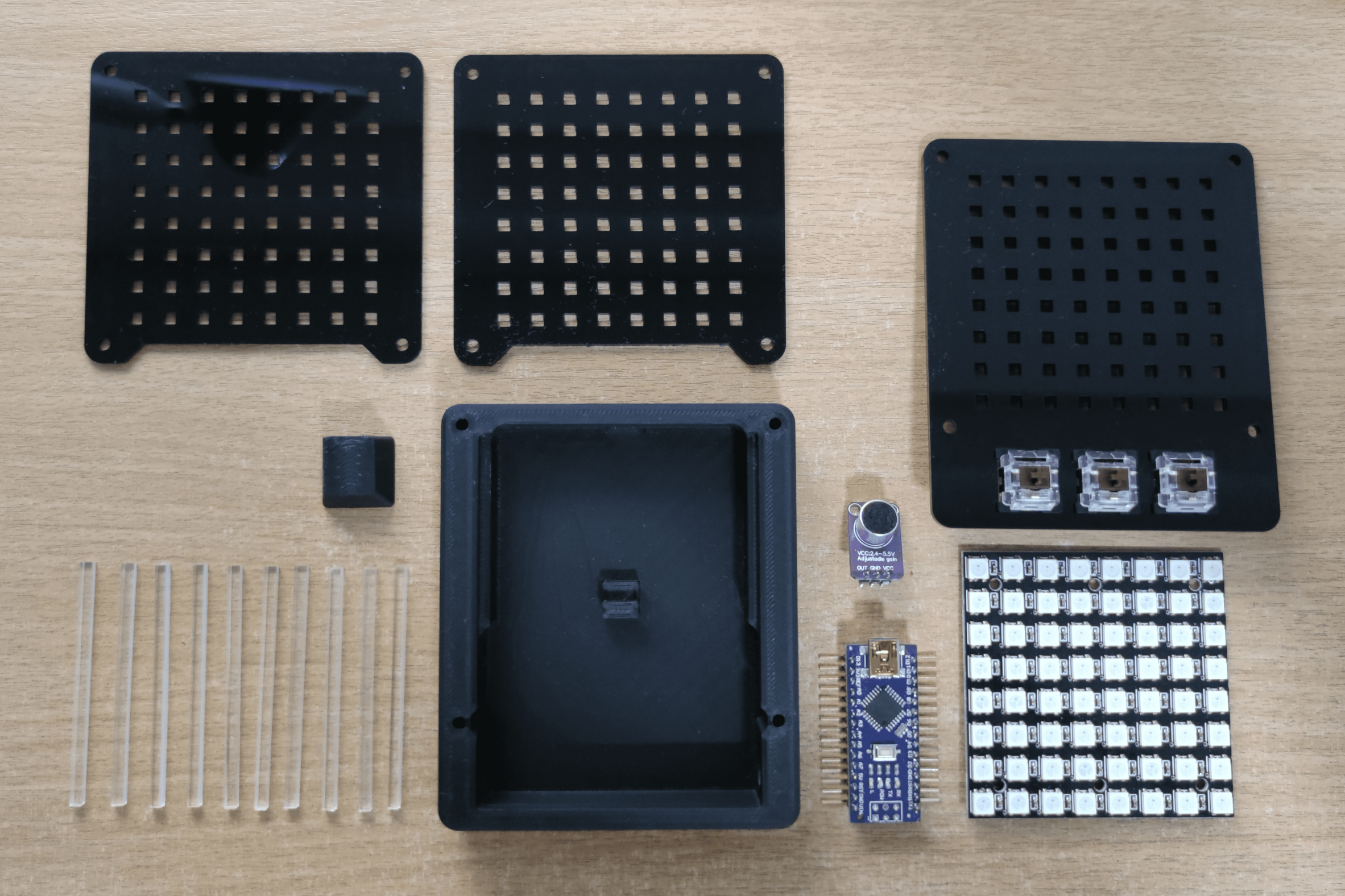
Assembly Parts
Now I will be moving on to the assembly of my Final Project.
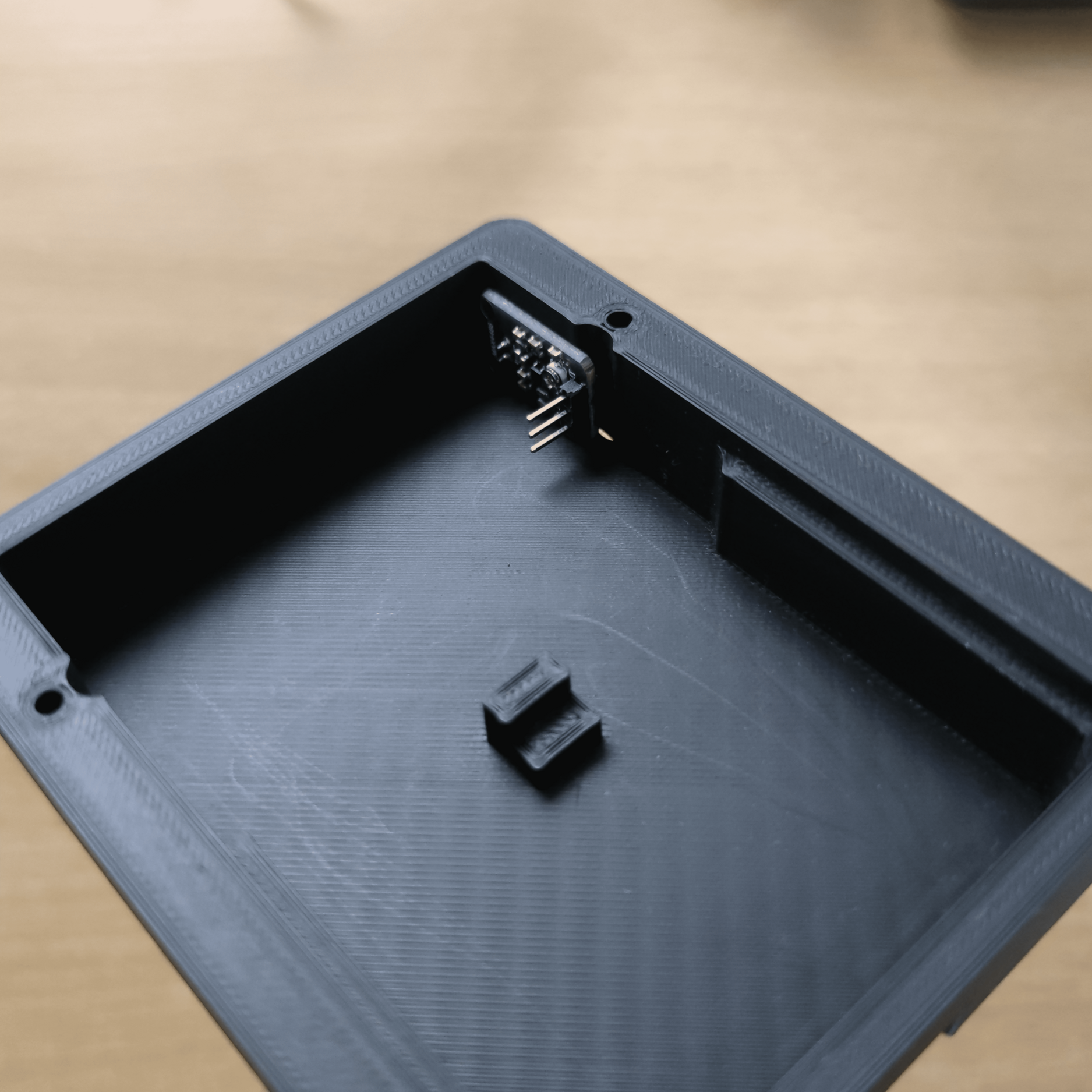
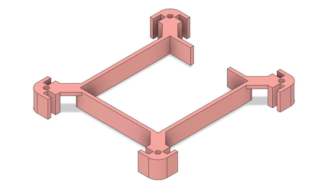
Microphone Mount
Nano Mount
First I mount the microphone and Arduino Nano into their respective mounting slots.
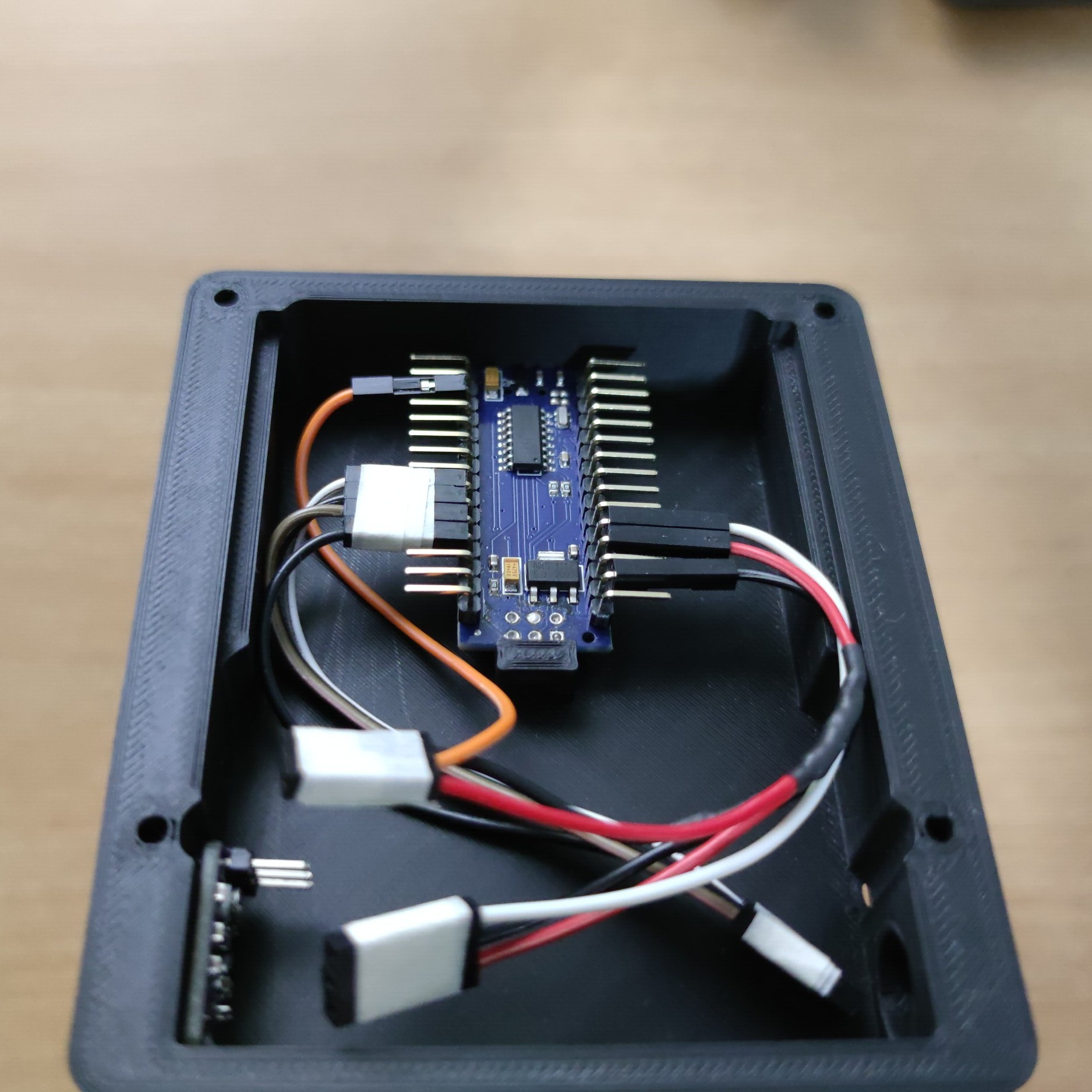
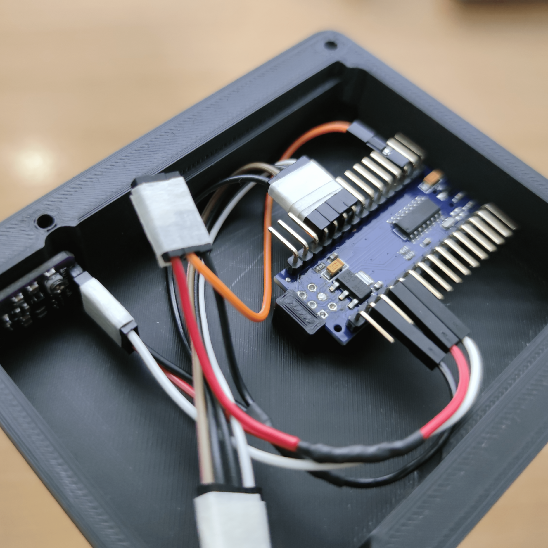
All Wires Connected to Nano
Connect Wires to Micrphone
Next, I carefully connect all the jumper wires to the Arduino Nano, making sure that bend in the right direction. I use duct tape to group the jumper wires together to make easier connections. Once that is done I can directly connected the wires to the microphone.
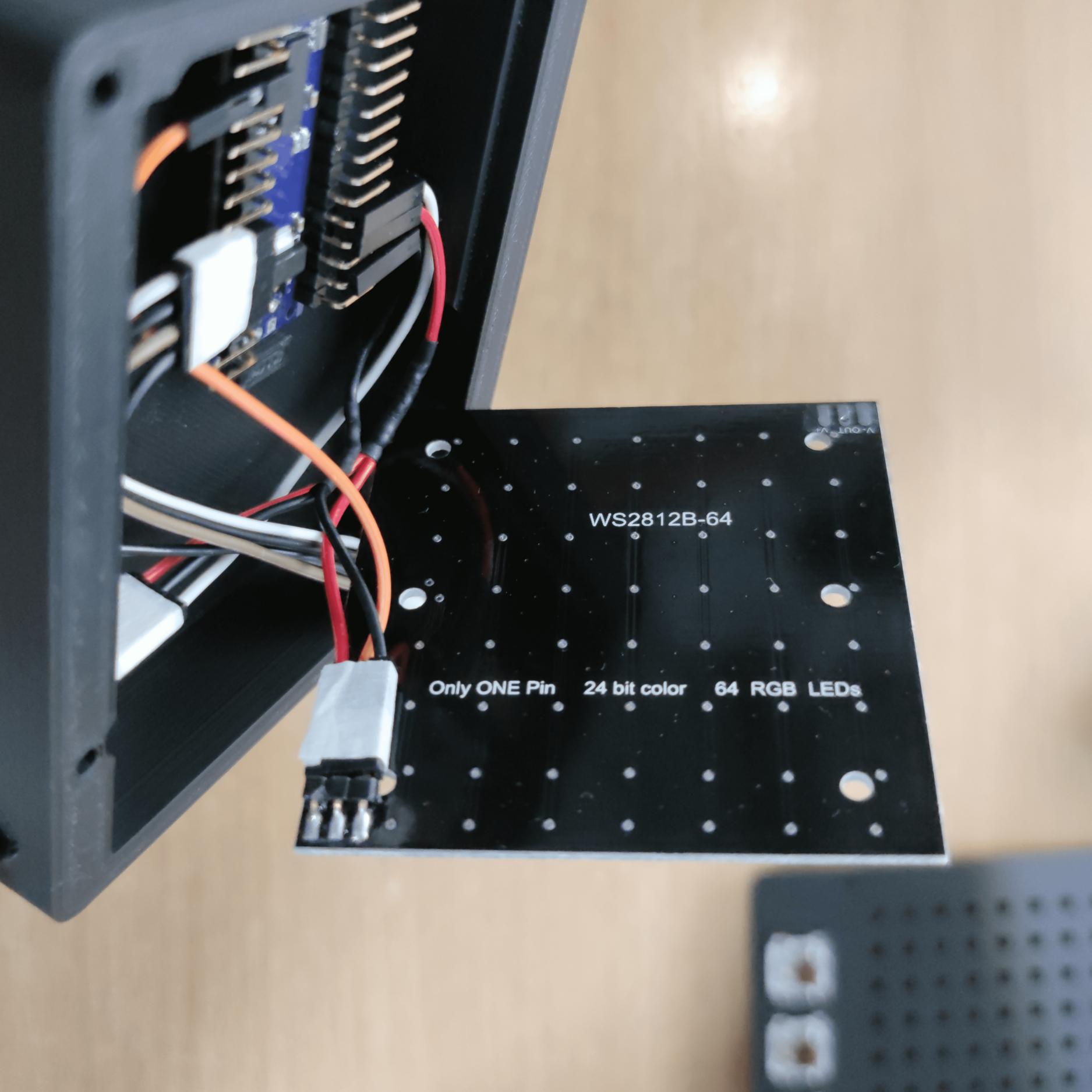
Connect Wires to Matrix
Matrix Mount
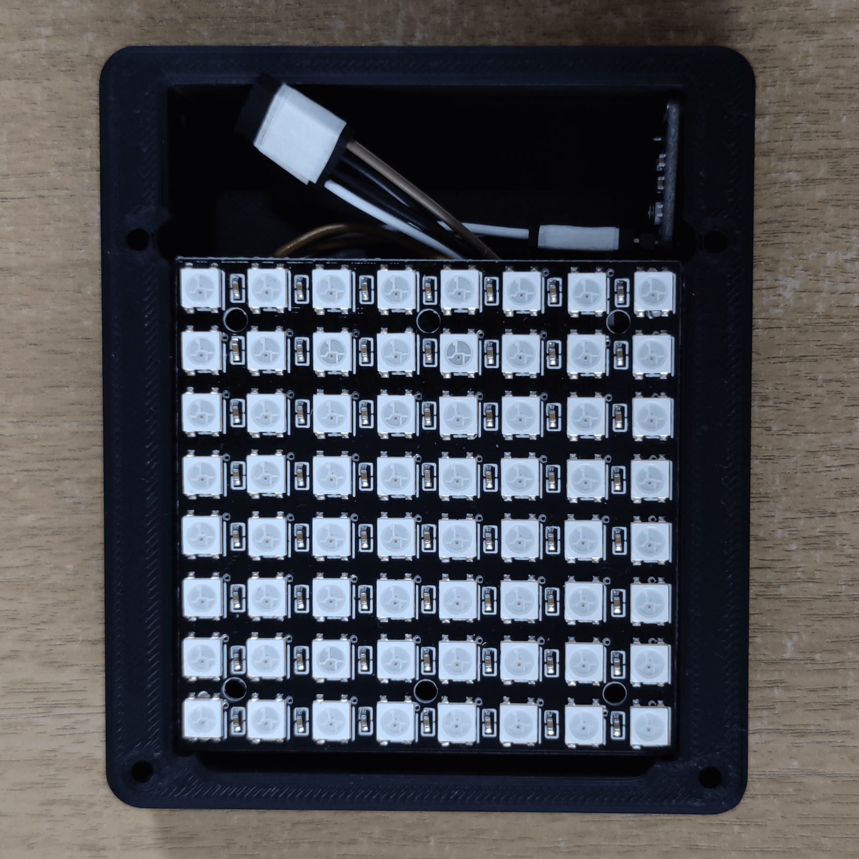
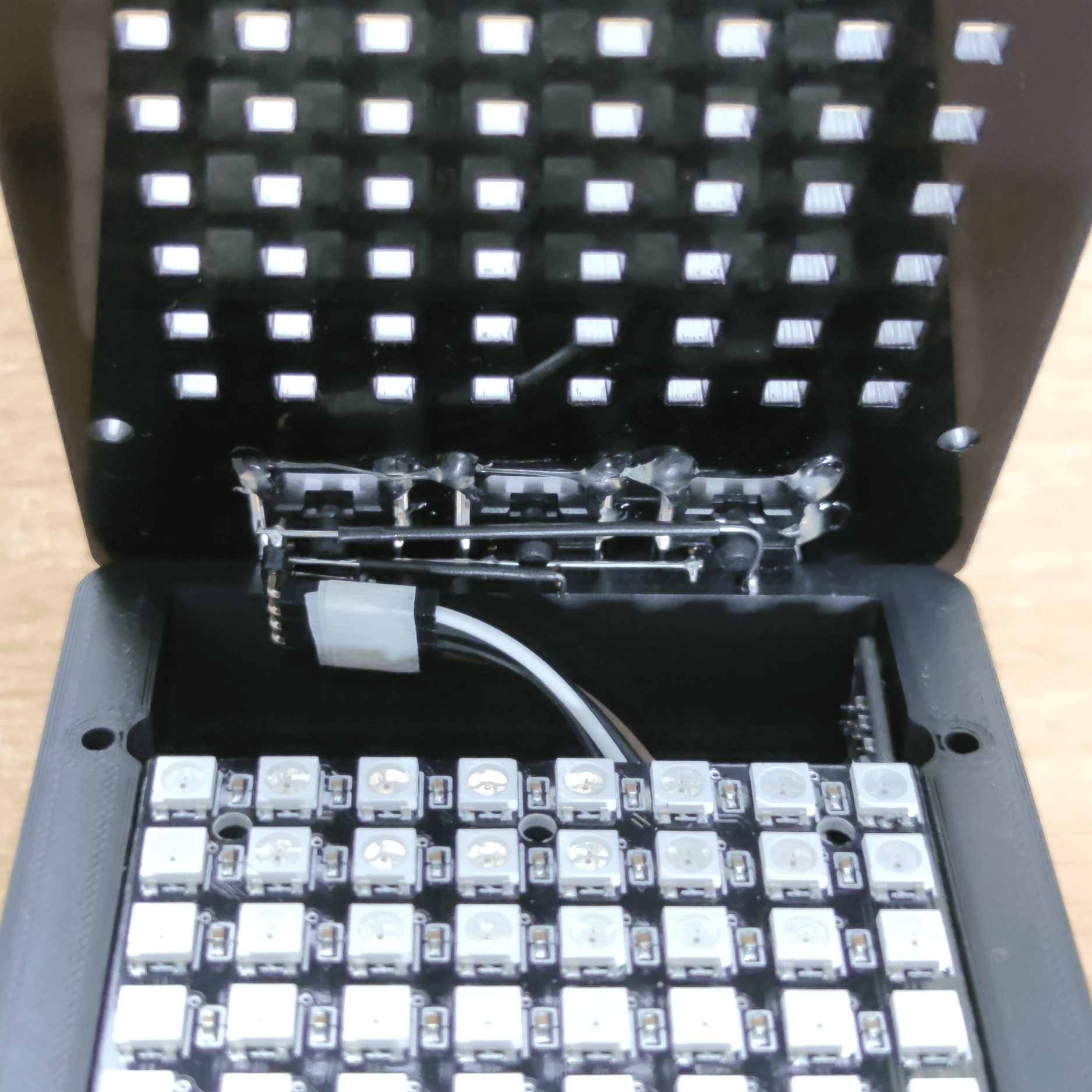
I connected the LED matrix and mount it onto the slot above the Arduino Nano.
Wires Underneath the Base
All the components from the base is connected will no errors. One final connection left are the 3 mechanical switches.
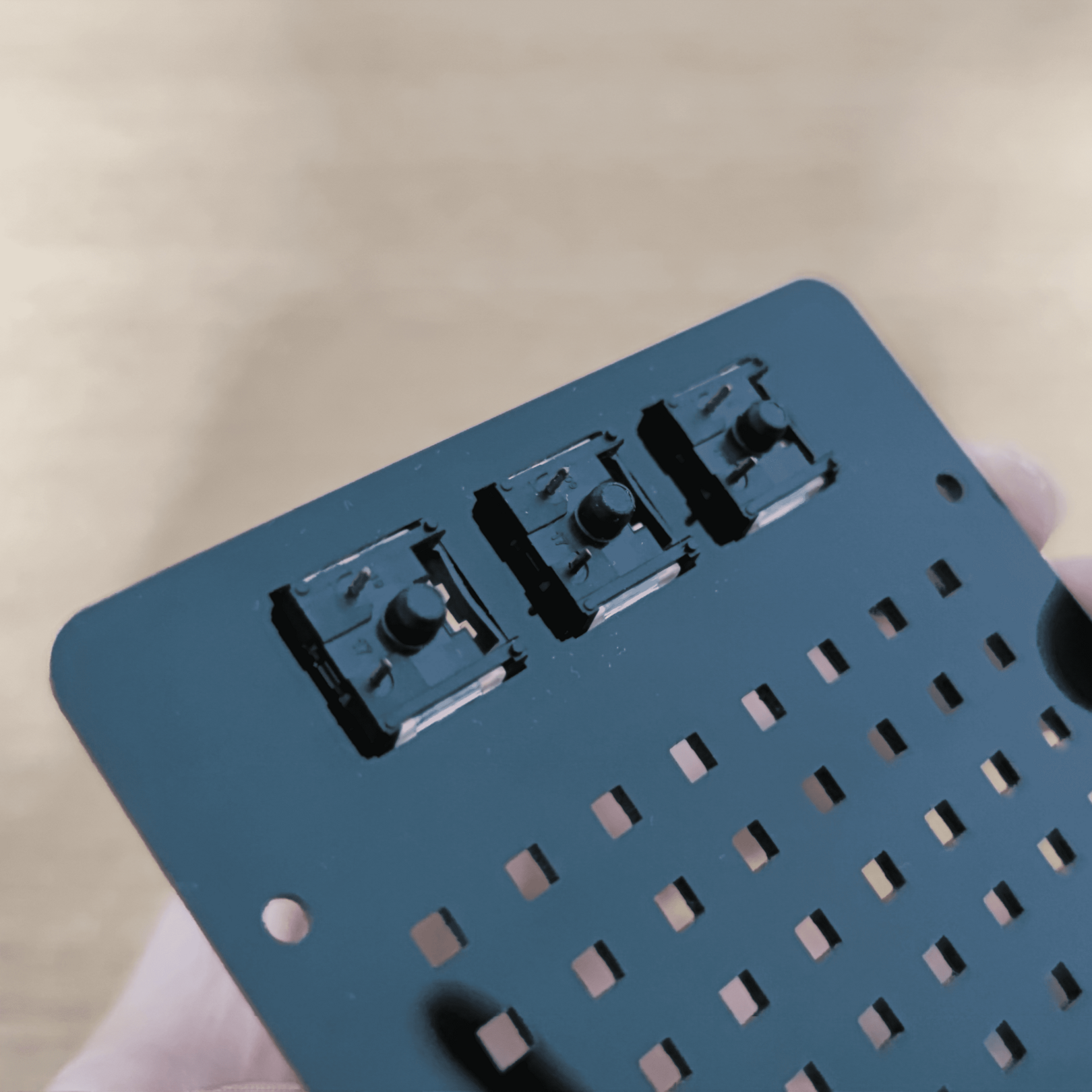
Mech Switches Mounts
Mech Switches Angled
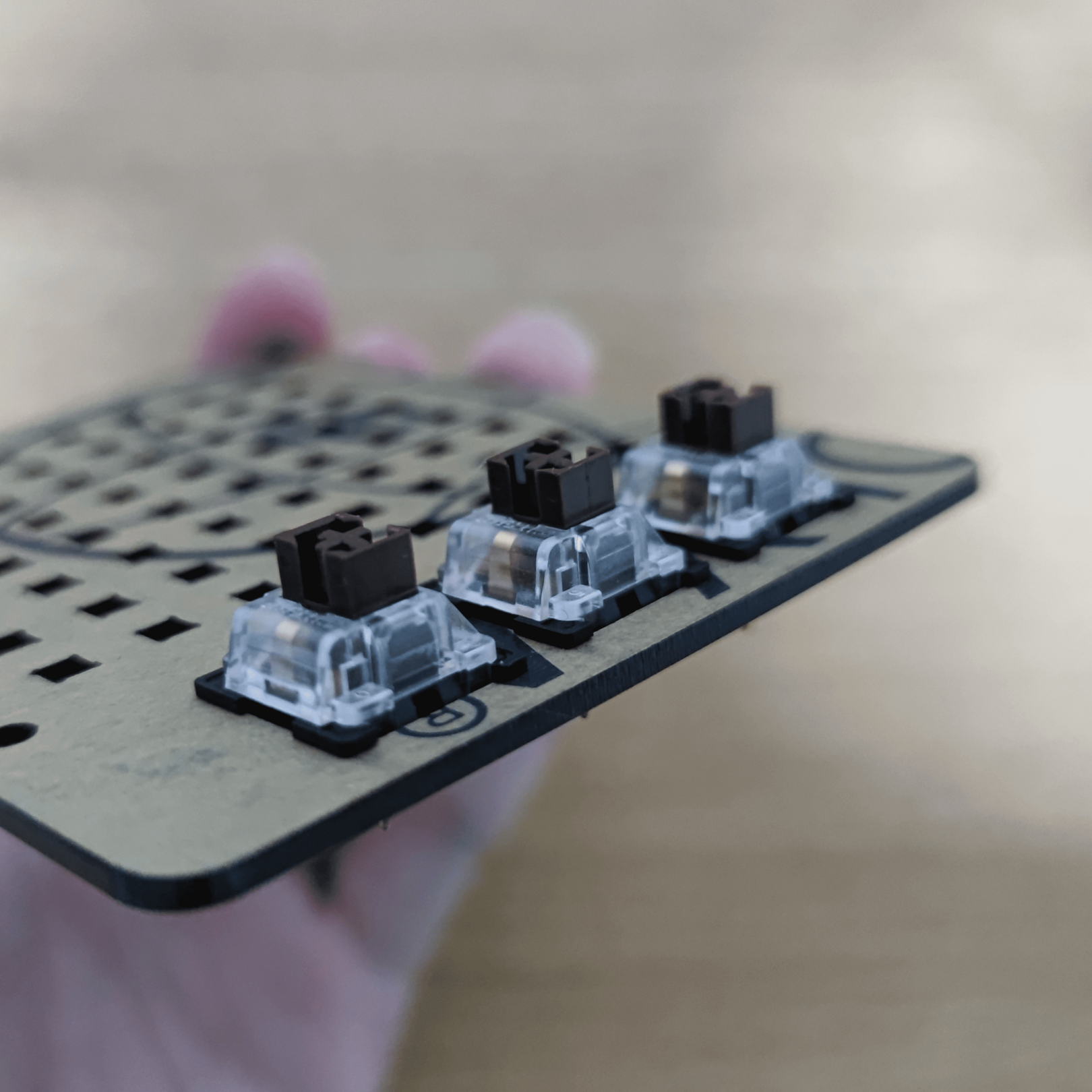
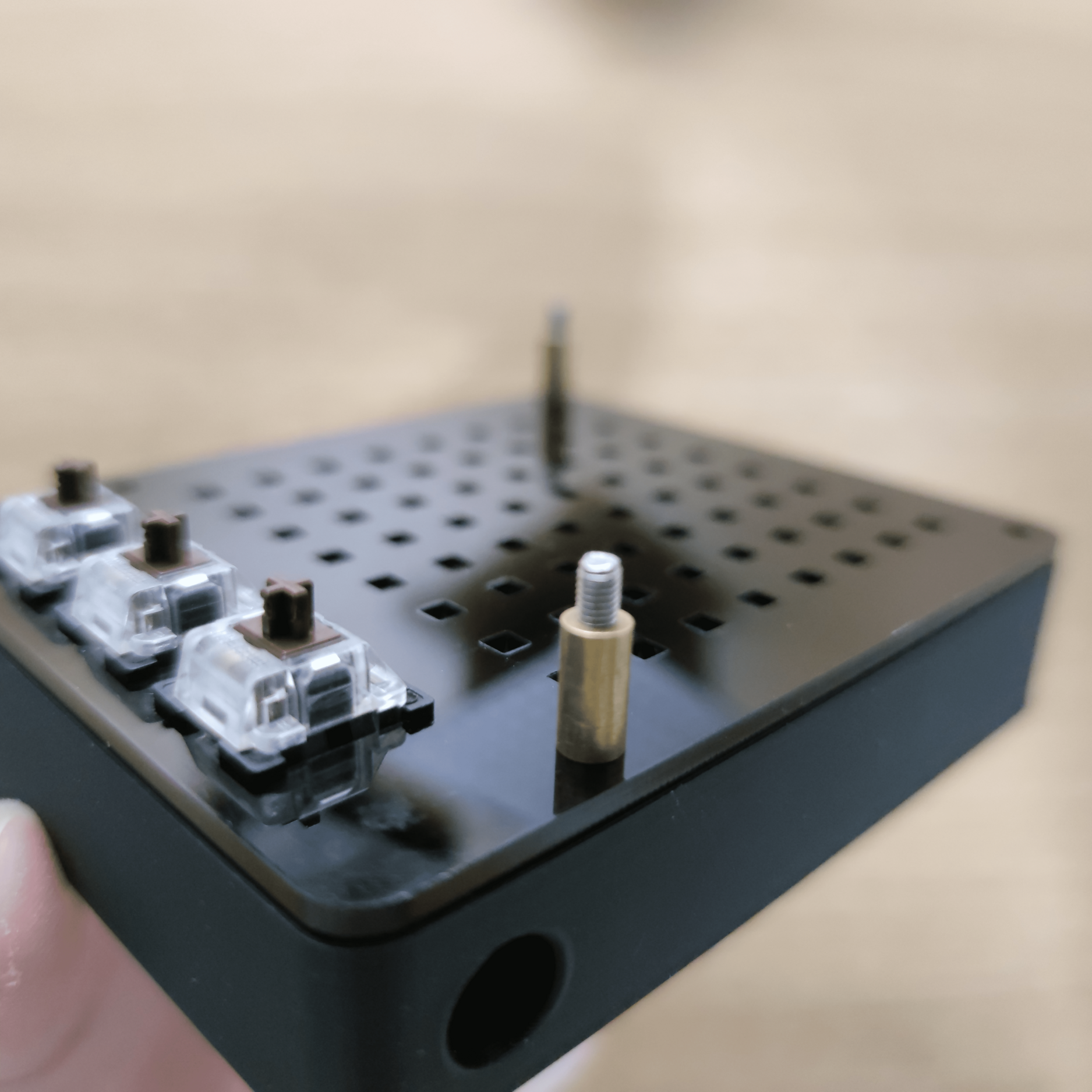
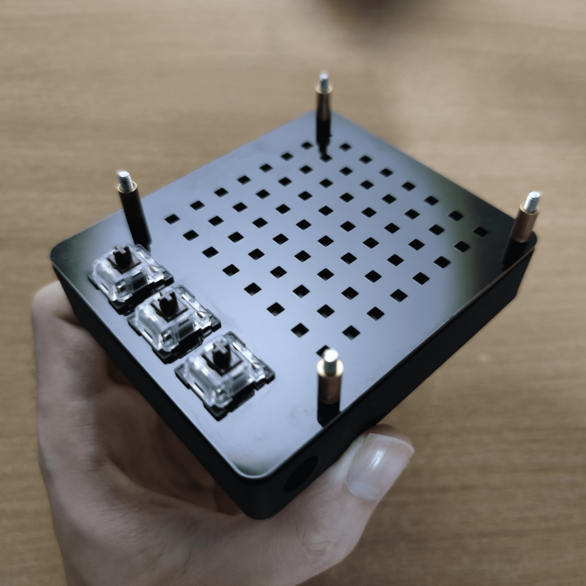
The mechanical switches nicely fit into the 14mm x 14mm hole. However, they are unable to clip onto the underside of the 3mm plate. Hence, I will need to hotglue them in place.
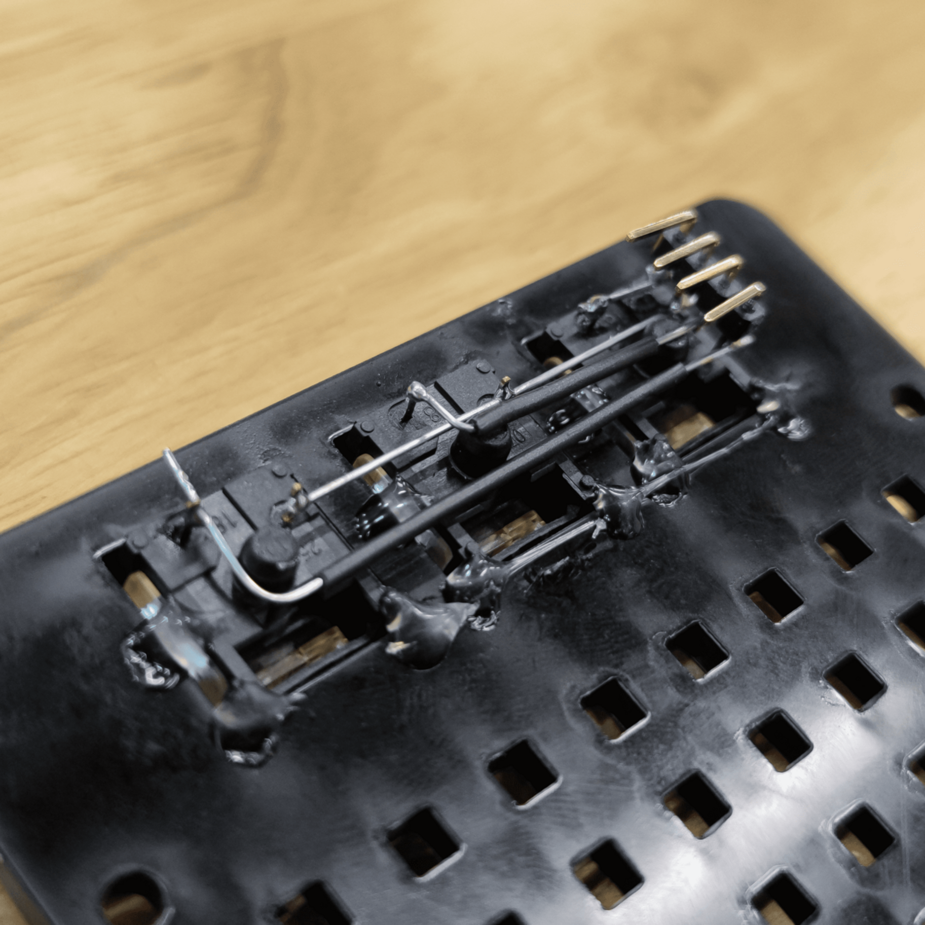
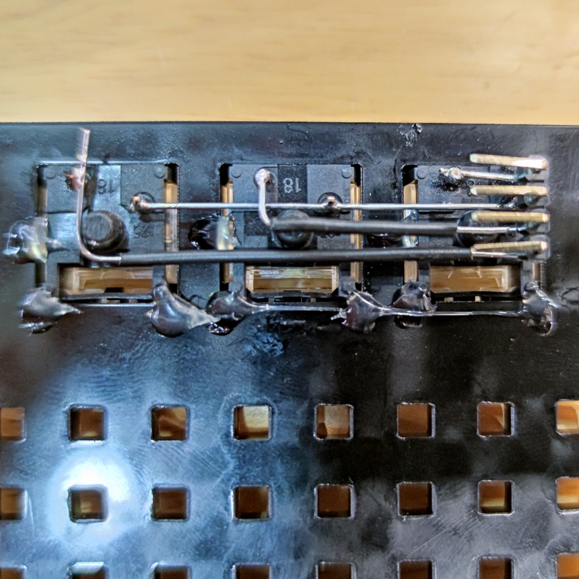
Mech Switches Soldered
Pins Soldered
I use Digital Input Pull-Up Resistor in my program for my mechanical switches. Meaning I will need to solder the 2 pins for each of the mechanical switches to the GND and Digital pins. To make the wire connections simpler, I use L-header pins as a connector for my jumper wires. The connection pins from top to bottom: D2, GND, D3, D4.
Connect Wires to Mech Switches
I connected the wires for the mechanical switches to the L-header pins.
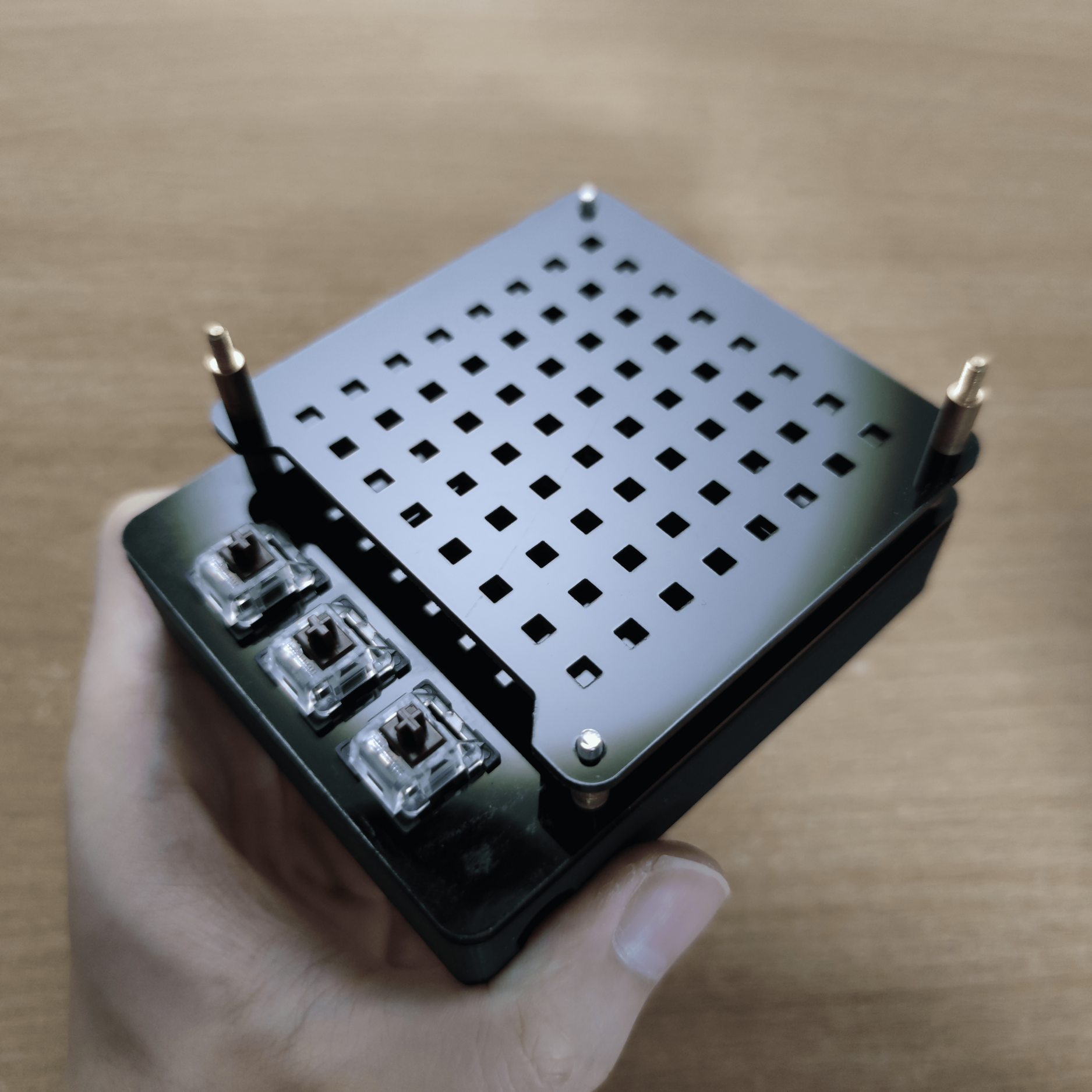
Hex Socket Screws & Spacers
Screwing Cover Plate
I screwed in M3x35mm Hex Socket from the bottom of the base through the cover plate and use 10mm spacer to hold the cover plate in place.
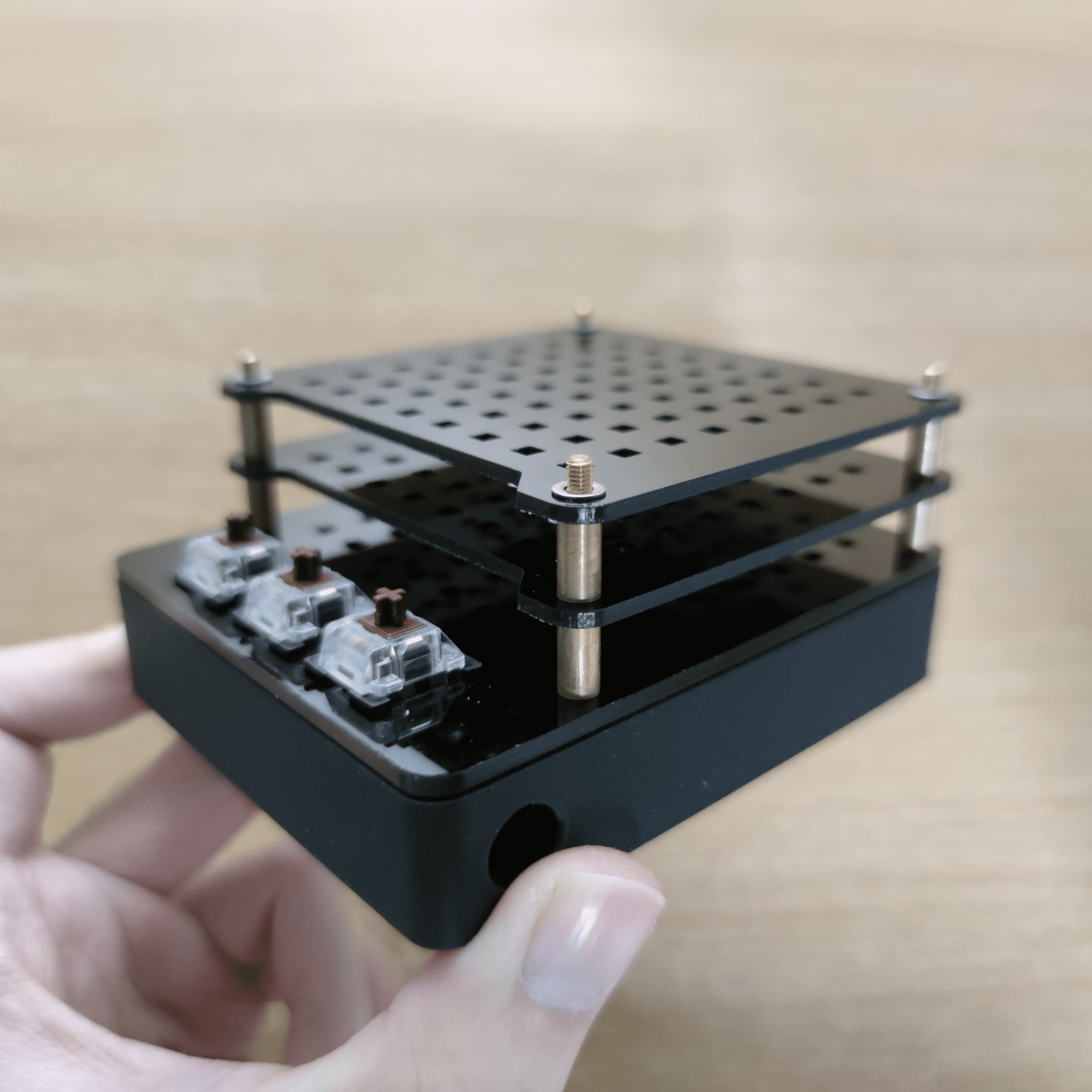
Screwing 1st Layer Plate
Screwing 2nd Layer Plate
I then stacked the layer plates above and use the same spacer to hold them in place. Once all the layers plates are stacked, I use M3x10mm Hex Socket screws to lock the structure in place.
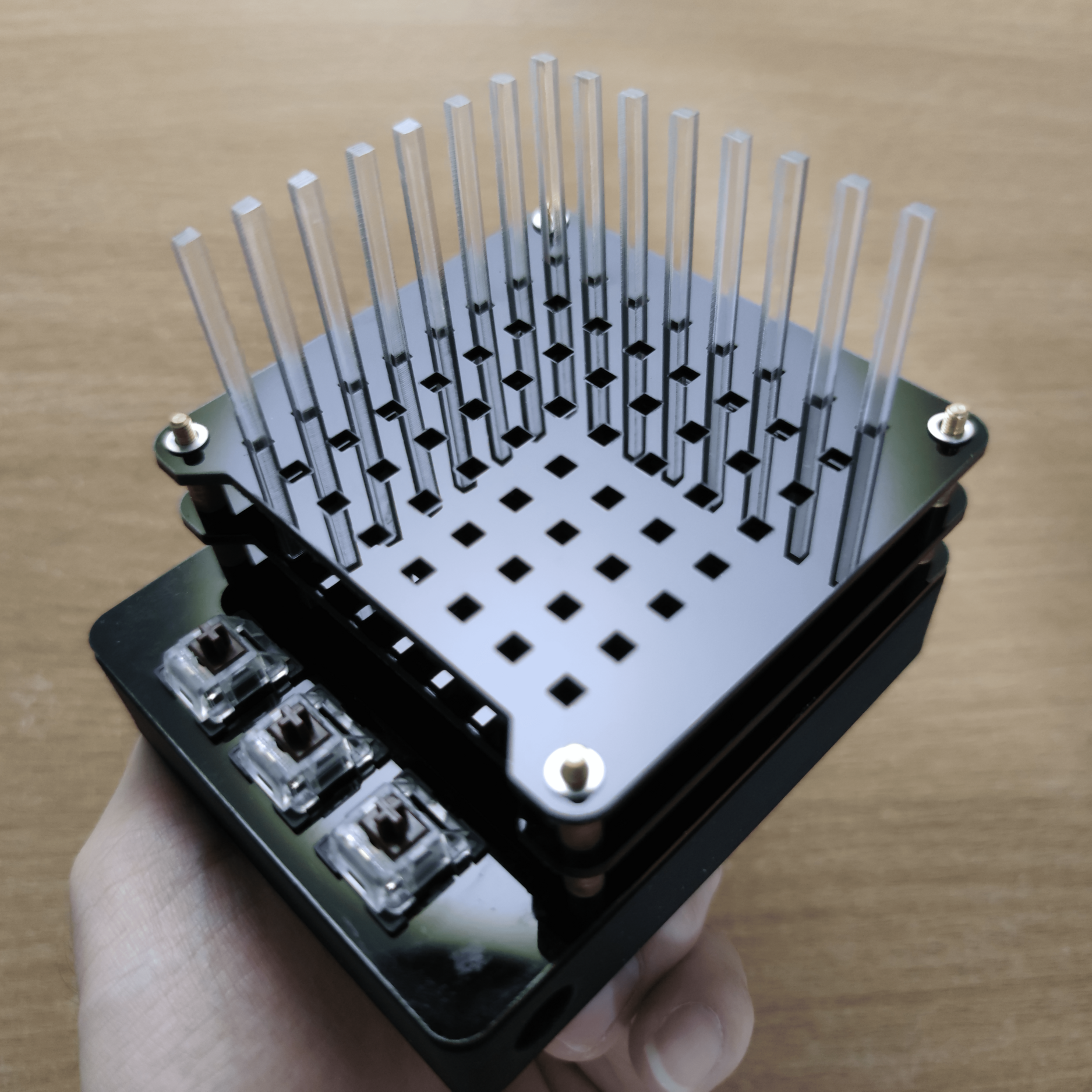
Slotting Acrylic Sticks
Finishing Slotting
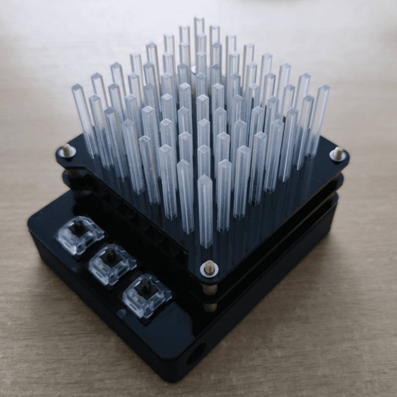
Finished Audio Visualiser
I place all the acrylic sticks into the holes which fits perfectly and firmly into the plates. Once that that is finished, the assembly is completed.
Challenges
Soldering Mech Switches
I find it challenging to solder the mechanical switches because of the uncertainty whether it is a viable method to solder on the 4 L-header pins. I was reluctant to try that at first and initially plan to solder the jumper wires straight away. However, doing so is extremely difficult as the wires are too short and impossible to solder on safely. Hence I decided to use L-header pins since the jumper wires are facing sideways. Soldering the the L-header pins was difficult too, but it was the only viable option then. I have to carefully bend and solder the wires to connect the mechanical switches to the legs of the L-header pins. The difficult part was that the tight space between the legs to solder on the wires properly and I might risk melting the casing of the mechanical switch or the L-header pins. With patience and steady hands, I successfully solder the wires in with no disconnections. Though the L-header pins might break off when connecting to the jumper wires in, it is soldered to 4 other wires so it should be sturdy enough to connect.
Areas of improvement
What I think can improve in terms of the design is the cover plate. Hotgluing components is a mess especially for smaller projects such as this. Hence, 3D print the cover plate of smaller thickness for the mechanical switches to clip into. Another improvement is to the base design as 3 hours of 3D printing may be too long. What might be worse that the design might fail and have to wait long hours for another print. I can redesign the 3D-printed base walls with slots that fit lasercut acrylic pieces. The 3D printed design will definitely be shorter and use less filament.