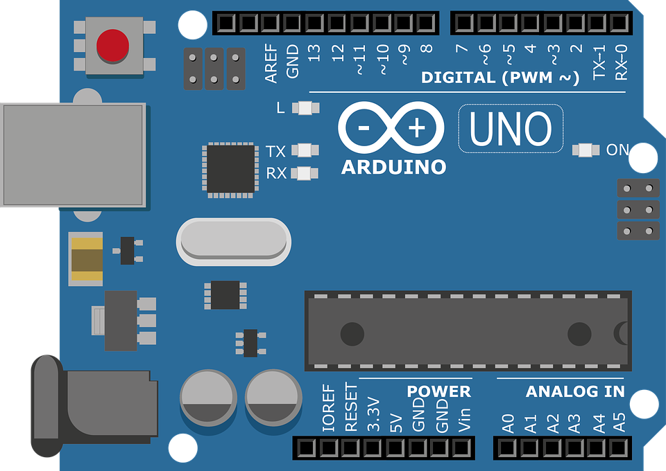
We are to write simple programs with the Arduino IDE and Uno R3 board. We test the programs on the TinkerCAD simulator first before wiring and implementing the actual circuits on the physical Arduino board. Here are the programming assignments:
This is an exercise to do a simple LED control using Arduino IDE. We are tasked to make the LED blink using delays.
Code
Defining Variables
#define is a useful C++ component that allows the programmer to give a name to a constant value before the program is compiled. Defined constants in arduino don't take up any program memory space on the chip. Then simply set the constants (LEDs) as OUTPUT Pins.
Code
Blinking LEDs
In a loop, to make the LED to blink, I added delays in between the HIGH and LOW values of the each LED digital pin.
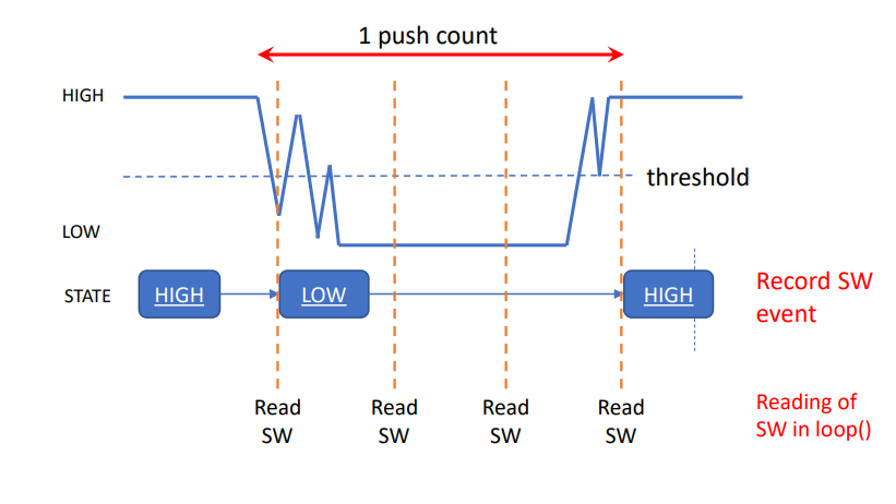
One of the issues faced was the bouncing of the switch that might cause incorrect states to be read. Without proper debouncing, multiple inputs may be read in quick succession when only a single input is intended, which will cause issues in the code. Also take note that this button in this assignment is Active LOW.
Code
millis()
Before explaining the code, it is important to understand millis(). millis() returns the number of milliseconds passed since the board began running the program. It acts as an internal clock and will be used multiple times during the program. The data type millis() use is unsigned long. Hence startPressed, debounceDelay and pressDelay are unsigned long data types. Just like above exercise, each LED and button was assigned to a pin and variables are declared.
Code
Debouncing Loop
Next is the debouncing loop. First, the button reading is constantly taken. Once the button is pressed and the reading changes, the time millis() is taken and stored as the startPress. This condition only triggers once there is a change in the buttonState. Note that due to the bouncing of the switch, multiple readings will be taken and stored in quick succession.
Code
Change Condition
At the same time, the difference between the current time and the stored startPress is constantly being calculated. Once the difference exceeds the value set by debounceDelay (50ms), it means that the switch has not "bounced" for 50ms and the input has settled. The next part of the code will be executed. The program will need to check if buttonState has changed and if the reading of the button is LOW (pressed), it will incease LEDState by 1. The LEDState refers to the cases of the switch function. Once it reaches '5', the counter will reset to '0' since (5%5) will give a remainder of 0.
Code
Off Condition
To turn off all the LEDs after pressing down the button for 3s, another 'if' statement is used in the loop. It works in the same way previous condition, where it compares the startPress and the current time and finds it difference. Once the difference exceeds the pressDelay (3000ms), and the button reading is LOW (pressed), the LEDstate is '0', turning the LEDs off.
Code
Update
The lastButtonState is also being continously updated. During all this, the function 'decode' has been continously run and change in LEDState will cause a switch case.
Code
Switch
The function decode contains the switch cases to control the LEDs. To make it blink, instead of delay, millis() was used. Adding delay is possible but however, the program is unable to detect another button press if the LEDs are blinking during the delays. To have the LEDs blink using millis(), the reading at a certain point in time and finds the remainder when divided by 2, which results in either a '0' (OFF) or '1' (ON). However, just using millis() will cause the LED to blink every millisecond, which would be too fast. As such, the reading is divided by 100, which will cause it to blink every 100ms as it will round the value to the nearest 100ms. The blinking intervals can be changed by changing this value.
Sensors & Libraries
Requirements
What to do
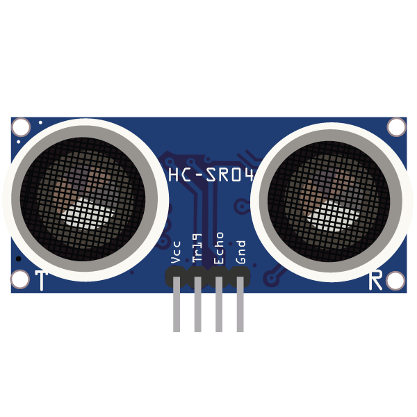
The fablab provides some useful components such as the ultrasonic sensor (SR04), humidity & temperature sensor (DHT11) and PIR motion sensor. The components have libraries ready to use so that coding will be easier. Here are the programming assignments:
Note that this tinkerCAD program does not actually work. This is to show how the circuit is connected to the sensor.
Code
Ultrasonic
The library I use NewPing.h. TRIGGER_PIN, ECHO_PIN & MAX_DISTANCE are defined as the input pins and the maximum sensing range of this ultrasonic. I need to set the pins connected and use sonar.ping_cm() to output the distance of an obstructing object.
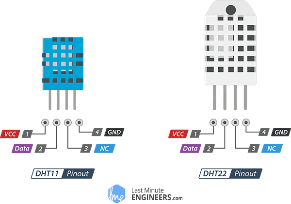
This is an illustration of the types of sensors DHT have. Currently, I am programming on the DHT11. The circuit connection is pretty simple as there are only 3 wires need to be made: VCC, GND & DATA. NC does not need to be connect because it means "Not Connected".
Code
RH & Temp
The library I use DHT.h which works similarly like the above program. DHTPIN and DHTTYPE are defined as the input pin and the type of sensor I am using. The program is pretty straight forward as I just need to use the library's function to output the data from the sensor.